Basic principle of CAN bus data exchange
In order to improve the reliability of data transmission, the two wires (twisted pairs) of the CAN data bus system are used for different data transmissions, respectively, which are CAN-HIGH and CAN-LOW lines.
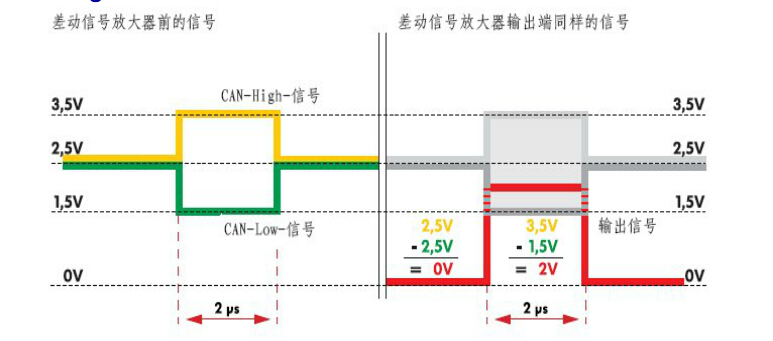
In the quiescent state, the effects on the two wires have the same preset value, which is called electrostatic flat. For the CAN drive data bus, this value is approximately 2.5V.
The electrostatic level also becomes recessive because all control units connected can modify it. In the dominant state, the voltage on the CAN-HIGH line will rise by a predetermined value (this value is at least 1V for the CAN drive data bus). The voltage on the CAN-LOW line is reduced by the same value (this value is at least 1V for the CAN drive data bus). Therefore, on the CAN drive data bus, the CAN-HIGH line is active, the other voltage is not lower than 3.5 (2.5V+1V=3.5V), and the voltage value on the CAN-LOW line can be reduced to 1.5V (2.5V). -1V = 1.5V).
Therefore, in the invisible state, the voltage difference between the CAN-HIGH line and the CAN-LOW line is 0V, and in the dominant state, the difference is at least 2V.
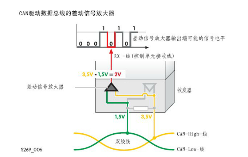
The control unit is coupled to the CAN drive bus via a transceiver having a receiver within the transceiver that is mounted on the receiving side of the differential signal amplifier. The differential signal amplifier is used to process signals from the CAN-HIGH and CAN-LOW lines, in addition to transmitting the converted signal to the CAN take-over area of the control unit. This converted signal becomes the output voltage of the differential signal amplifier.
The differential signal amplifier subtracts the voltage on the CAN-LOW line (UCAN-LOW) from the voltage on the CAN-HIGH line (UCAN-HIGH), and the input voltage is obtained. This kind of aromatic can eliminate the static electricity (for The CAN drive data bus is 2.5V) or any other overlapping voltage.
Since the data bus is also arranged in the engine compartment, the data bus is subject to various disturbances, and the short circuit to the ground and the battery voltage, the spark discharge of the ignition device and the static discharge should be considered during maintenance.
Since the CAN-HIGH line and the CAN-LOW line are twisted pairs twisted together, the interference pulse always acts regularly on the two lines. Since the differential signal amplifier always subtracts the voltage on the CAN-LOW line from the voltage on the CAN-HIGH line, there is no more interference pulse in the differential signal after this processing.
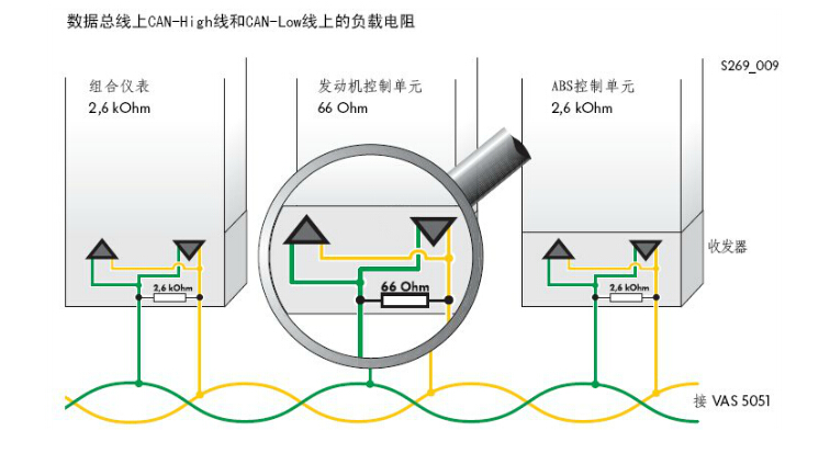
The task on the transmitting side of the transceiver is to amplify the weaker signal of the CAN controller in the control unit to the signal level on the CAN conductor and the signal level at the input of the control unit. The control unit connected to the CAN data bus acts like a load resistor on the CAN conductor (because of the electronics), which depends on the number of control units connected and their resistance.
The transceiver delivers the CAN signal to the two conductors of the CAN data bus, and accordingly the voltage on the CAN-HIGH line rises and the voltage on the CAN-LOW line decreases by the same amount. For driving CAN bus data, the voltage change value on one wire is not less than 1V, and for CAN comfort/Infotainment bus, this value is not lower than 3.6V.